Repairing the Contax 167MT
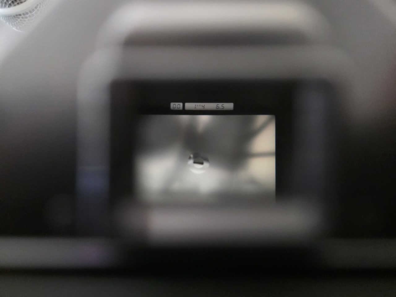
While looking on Facebook Marketplace I stumbled upon a listing for this Contax 167MT. It was a gift from a friend who had passed away, and the seller gave it to me for free after seeing my photography and wanting it to be used. While testing the body out, I discovered that the little display showing the aperture and shutter speed information in the viewfinder was not showing up properly.
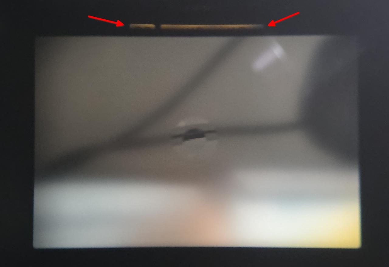
Unfortunately there is little on the Internet about the exact process of repairing this camera, or this specific issue, for that matter. In this post I detail the process of removing the top cover from this camera to fix this issue.
Removing the top cover
After scrounging around for tutorials or guides, I managed to find Contax 139 Resource, a website hosting repair manuals for Contax cameras. The guides made it clear that removing the top cover was necessary to solve my issue.
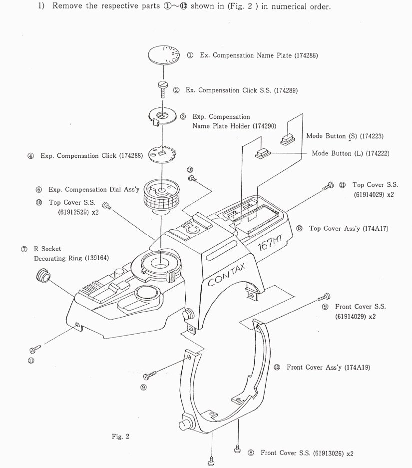
Following part B of the repair manual, page B-2, there are a total of six screws that are easy to remove: two next to the viewfinder (Top Cover S.S. 61912529), two near the camera strap eyelets (Top Cover S.S. 61914029), and two just below the Contax logo (Front Cover S.S. 61914029).
Next, a small plastic ring which surrounds the remote shutter release (R Socket Decorating Ring 139164) needs to be removed. This is best done with a rubber friction tool. The YouTube video below shows this procedure at 5:10.
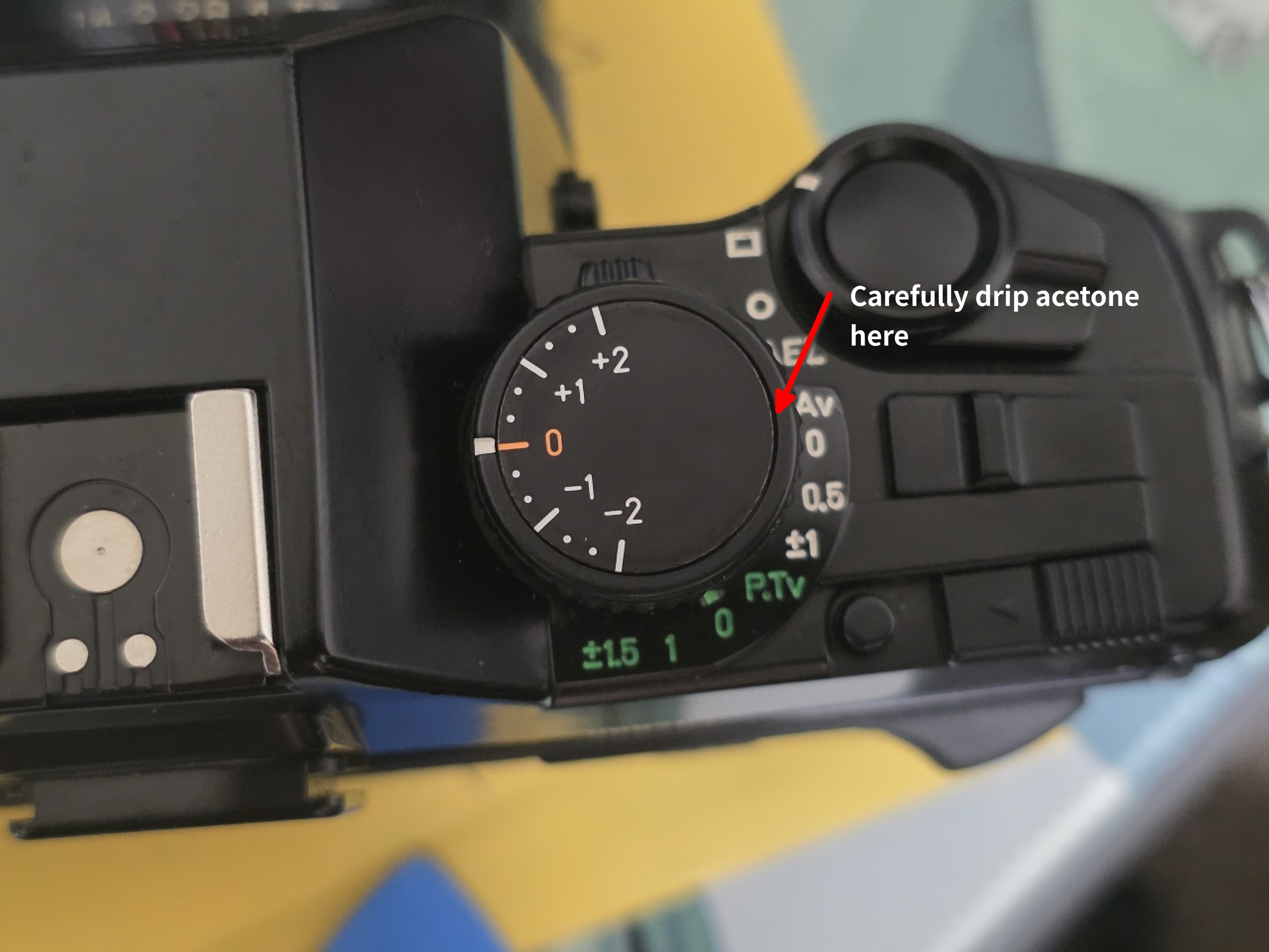
Lastly, the exposure compensation dial needs to be removed. The top plate (Ex. Compensation Name Plate 174286) is made of metal and is glued down firmly to the screw below it (Ex. Compensation Click S.S. 174289). I tried lots of isopropyl alcohol and heat with an iFixit iOpener to no avail. Finally I tried some acetone, and with some prying with a thin metal spudger, I was able to remove the plate off. However, the plastic of the compensation dial (Exp. Compensation Dial Ass’y) reacts to the acetone, and I messed up a bit of the finish on the dial. I would suggest using a syringe with a fine needle to carefully add some acetone in the small gap between the top plate and plastic dial, and letting the solvent dissolve the glue to avoid damaging the plastic.
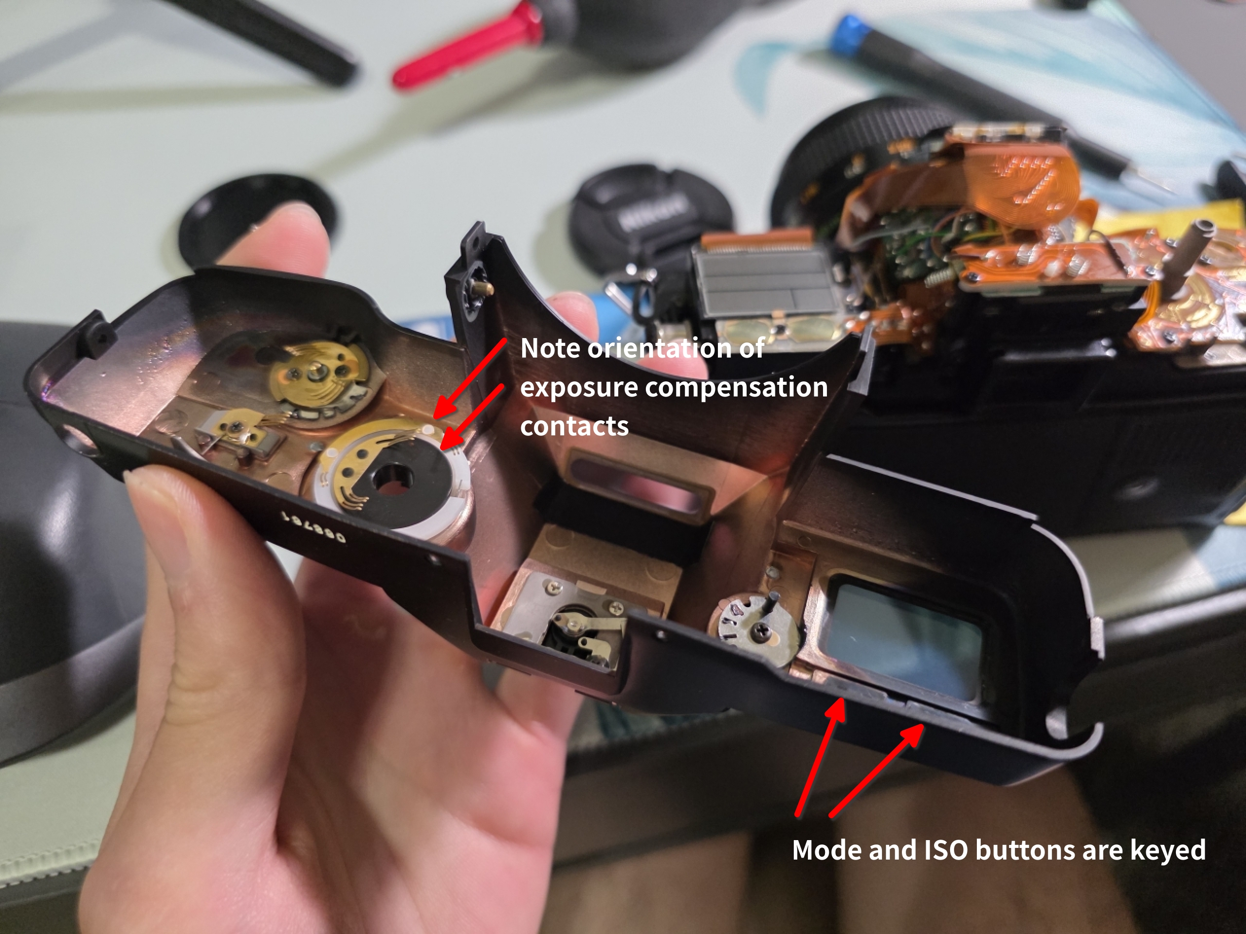
When pulling the top cover off, be careful as the mode and ISO buttons will fall out.
Adjusting the finder display
Once the top is removed, adjusting the finder is relatively straightforward. In parts C and D of the repair manual, section C-4 (page C-13) details the finder display adjustment screw. There is some adhesive locking down the position of this screw which can be scratched off or carefully softened with a dab of isopropyl alcohol. It appears that this camera’s positioning was probably defective from the factory as the adhesive was still intact!
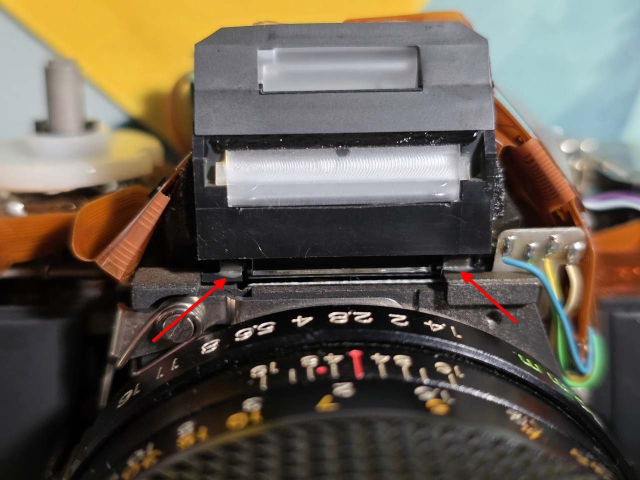
The screw can then be adjusted with a flat-head screwdriver bit. Adjusting the mirror toward the body will raise the position of the finder display relative to the viewfinder, and vice versa.
When putting the camera together, I suggest holding the top cover upside-down so the buttons and exposure dial contacts can be placed without falling out. Take note to not catch the cover on the metal of the remote shutter release while attaching the top.
And here is the end result. Success!
